
As you can see they are based on an SMD version of the MAX3232 IC and each end is labelled with data in, data out, and +/- power connections.

The PCBs are double sided and as I understand it there are two separate comms channels - one on each side of the board. The modules are so small that I decided to solder one directly on to the back of a female 9 pin D connector so that once assembled it would be hidden inside the connector shell.
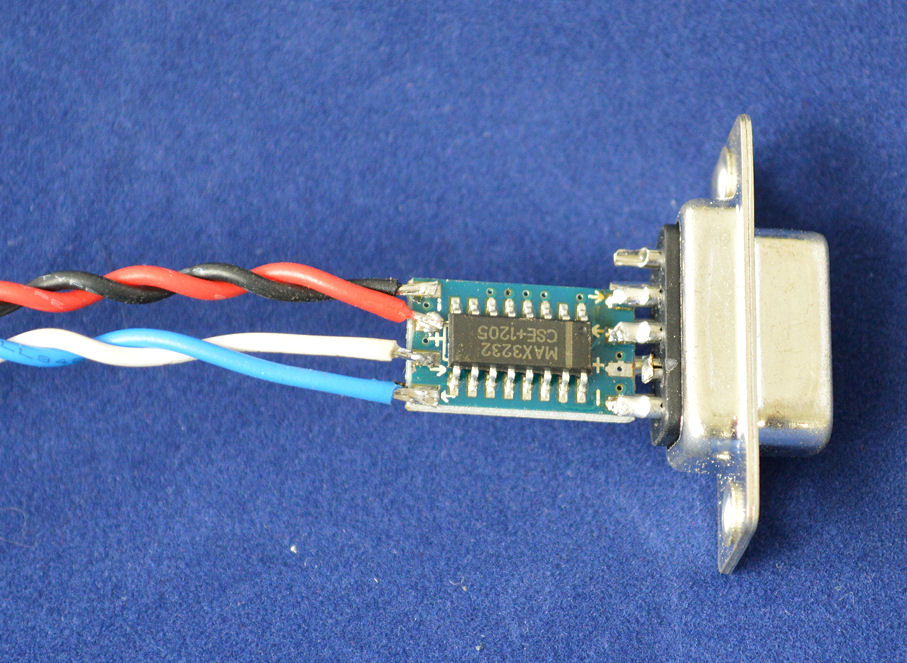
The output from the level shifter board (as indicated by the arrow) was connected to pin number 2, the input to the level shifter board (as indicated by the arrow) was connected to pin number 3, and the system ground (-ve) connection on the level shifter board was connected to pin number 5. Note that pin number 4 on the female 9 pin D connector was cut off so that it didn't inadvertently make contact with the +ve terminal on the level shifter board. As previously mentioned these boards are double sided so a small strip of insulating material (I used clear acetate sheet) was placed between the pins on the D connector and the terminals on the other side of the level shifter board to prevent inadvertent connections being made. Finally wires were carefully soldered to the pads on the opposite end of the level shifter board and the complete assembly inserted into the connector shell.

Not forgetting to fit the cable grip before fitting the other half of the shell.

The finished item, assembled and ready to go. I have a limited number of these ready built and tested units available for purchase from www.cutpricecables.co.uk for only £9.99 each inc VAT and UK delivery - please email me for details if you are interested.

The other ends of the wires are fitted with connectors that will attach directly to the GPIO pins on the Raspberry Pi.

These wires were connected to the GPIO header on the Raspberry Pi as follows. The data wires (white and blue) were connected to GPIO 14 (TXD - pin number 8) and GPIO 15 (RXD - pin number 10) respectively. The ground connection (black wire) was connected to the ground pin (pin number 6 on the GPIO header), and the power connection (red wire) was connected to the 3.3V power pin (pin number 1 on the GPIO header).

By default the serial port on the Raspberry Pi's GPIO header is configured to be used for console input/output. Therefore to operate the Raspberry Pi in "headless mode" (i.e. via a console interface on another computer) all that is required is to connect the female 9 pin connector to the serial port on another computer (or to a USB to serial interface connected to another computer) and then run a terminal emulation program on the other computer. Details of how to do this will be the subject of my next post.
No comments:
Post a Comment